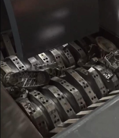
Industrial Blade Failure Analysis: Diagnosing Chipping, Cracking and Premature Wear
When a blade fails early, the first explanation is almost always the same: the steel was not hard enough. Acting on that answer is how a plant ends up replacing the same set twice in one season. Chipping, cracking, accelerated wear and deformation are four different damage mechanisms with four different causes and for two of them, raising hardness makes the failure arrive sooner, not later. This guide works backwards from the damage: how to read a failed edge, which measurable parameters to check before you blame the material, and where the line sits between regrinding and replacement.
Start with the damage, not the steel. Classify the failure — chipped, cracked, worn or deformed — then check clearance and alignment, then review what the machine was fed, and only then open the material and heat-treatment records. In most premature failures the blade is the last link in the chain, not the first: it is simply where an upstream condition finally becomes visible.
Key Takeaways
- Every failed blade belongs to one of four families: chipping, cracking, accelerated abrasive wear, or deformation. Each one has a different fix, and two of them get worse when hardness is increased.
- The visual signature of the edge tells you which mechanism dominated; the mounting interface tells you where the load that caused it came from.
- Clearance, alignment and guide wear are the most common hidden causes of damage that looks like a material defect.
- A chip is a crack initiation point. Dismissing small chips as normal edge wear is how a set gets retired early.
- Track blade life in tonnes processed, not calendar weeks, or normal wear and abnormal wear will look identical on paper.
- Regrind while geometry and crack-free material remain; replace as soon as a crack has entered the blade body.
How to Read a Failed Blade: Four Failure Families
Before opening the material certificate, look at the damage. Almost every failed edge belongs to one of four families, and the shape of the damage already narrows the cause before a single measurement is taken.
Four families, four different fixes. A chipped edge and a rounded edge can look similar on a worn-out blade, but they demand opposite responses: one usually means the blade is too hard for its load, the other that it is too soft for its feed. Treating both as "worn out" is why the replacement fails the same way.
| Failure mode |
Visual signature |
Dominant mechanism |
First check |
| Chipping |
Small irregular breaks along the cutting edge with bright, fresh fracture faces |
Impact load exceeding edge toughness; tramp material; clearance too tight |
Inspect the feed for unshreddables and measure clearance |
| Cracking |
Hairline cracks at holes, keyways and corners, or running through the body — often with a serviceable-looking edge |
Stress concentration, fatigue, thermal cycling, grinding damage |
Check mounting fit, bolt torque and alignment before the steel grade |
| Accelerated abrasive wear |
Even edge rounding, polished flanks, measurable loss across the whole edge |
Abrasive contamination in the feed; hardness window too low; excessive clearance |
Compare wear across the full edge and review feed cleanliness |
| Deformation and heat checking |
Bent or bowed blade, upset punch face, bulged bore, fine surface crack network |
Overload, compressive fatigue, friction heat, inadequate support |
Check seating, spacers, lubrication and press setup |
Most real failures are a combination, and the order matters. Abrasion removes the support behind a thin edge; impact then breaks out what is left. Reading the sequence — not just the final appearance — is what tells you where to intervene.
What separates a clean cut from damage in the first place is the load path between edge and material. how shear and tear loads act on a shredder edge covers the mechanics that produce each signature above.
Chipping: When the Edge Breaks Out Instead of Wearing Down
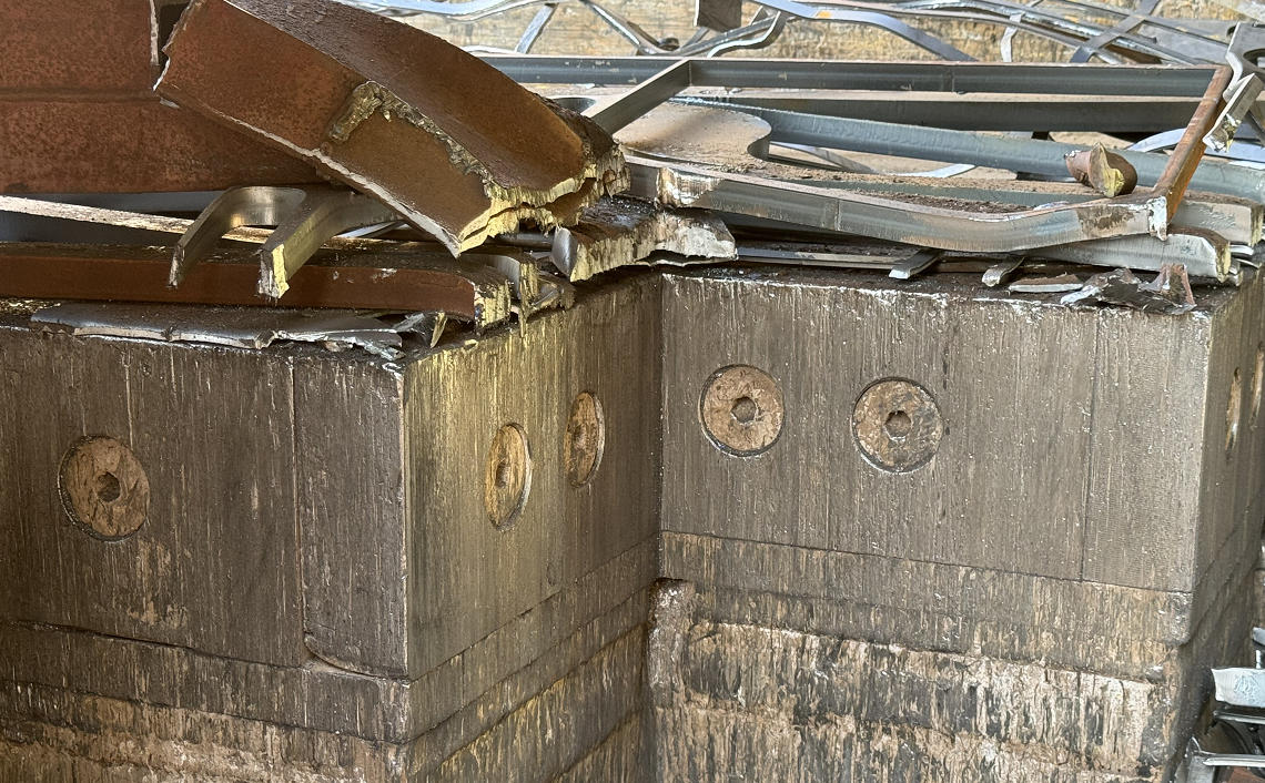
What a chipped edge tells you. Chipping always looks sudden, because it is: a fragment of edge leaves in one event rather than wearing away over time. Fresh, bright fracture faces, irregular depth, and damage concentrated on one section of the edge rather than distributed along it are the usual signs. If the chips are deep and the undamaged edge still looks sharp, the blade was not worn out — it was overloaded.
The five causes behind most chipped edges.
- A hardness window above what the load allows. The single most common cause. The feed contains thick sections, castings or unexpected hard items, and the edge has no capacity left to absorb the impact.
- Tramp material. Unshreddables that slipped past sorting, or hard items that arrived inside the feed. Damage from this is usually localized and severe.
- Clearance too tight. Knives and counter knives contact each other under load, and repeated contact chips the edge from the side rather than the front.
- Oversized feed and batch overloading. Feeding above the rated size produces impact events the geometry was never specified for. Operators often describe this blade as "failing for no reason" because nothing in the blade changed.
- Inconsistent heat treatment. Surface decarburisation, insufficient tempering, or grinding damage left from the last regrind can leave a localized soft or brittle zone. Damage that appears in the same place on every blade from one batch points here.
What to check before you change the steel. Measure clearance. Ask what changed in the feed in the weeks before the failure. Inspect the opposing blade or counter knife, since chipping is rarely one-sided. Verify the blade seats flat and that bolts hold torque. Only when those are clean is changing the material grade the right move — and choosing it is a trade-off, not a ranking: steel properties that control edge toughness explains which properties actually set that balance.
Cracking and Catastrophic Fracture
Where cracks start. Cracks almost never begin at the sharpest point of the edge. They begin where geometry concentrates stress: bolt holes, keyways, sharp internal corners, the boundary of a ground area, or the base of an existing chip. A blade that comes out with cracks radiating from the bore while the cutting edge still looks serviceable is not a steel problem — it is an interface problem, and the next blade will do the same thing until the fit is corrected.
Thermal fatigue and heat checking. A fine network of shallow surface cracks is a different failure from a single propagating crack, and it comes from a different cause: repeated heating and cooling at the cutting zone. Heat checking does not usually destroy a blade on its own, but it removes the surface layer that supports the edge and gives every later impact a place to start. If the network is spreading, look at cutting speed, lubrication, and how much of the work has become rubbing rather than shearing.
Is it a crack or a scratch? Scratches follow the direction material flowed; cracks follow the path stress took. A scratch is mechanical marking. A crack will catch under a fingernail, appears darker under a light, and in most cases can be confirmed with dye penetrant. Any crack that has entered the blade body is a replacement decision, not a regrinding one — grinding can only remove what it can reach, and welding is not an acceptable repair for blade tooling.
Accelerated Abrasive Wear: When the Edge Rounds Too Fast
Normal wear versus accelerated wear. Normal wear is even, predictable, and measurable: the edge rounds gradually along its whole length, output stays consistent, and life between changes stays close to your own baseline. Accelerated wear is everything else — the same blade retiring at half its usual tonnage, wear concentrated at the feed side, grooves and polished areas on the flanks, or discolouration from friction heat.
What actually accelerates it. Abrasive contamination is the first suspect: sand, concrete residue and mill scale are harder than the tool steel and behave like grinding media inside the cut. Moisture makes it worse, because wet dust sticks to the material instead of being carried away. A hardness window set too low for the feed wears quickly under that load. Clearance that has opened too far turns a cutting action into a rubbing one, and a feed that lands unevenly across the cut wears one section of the edge before the rest has done its share.
Establish a baseline before you need one. Record tonnage processed per set, output size and power draw as a matter of routine. Without that record, "wearing faster than it used to" is an impression, not a measurement — and it is the measurement that tells you whether the cause is upstream in the feed or downstream in the tooling. the wear mechanisms behind fast scrap shear blade failure breaks the underlying drivers down in detail.
Plastic Deformation and Overload Damage
Deformation is the failure that most often gets misdiagnosed as wear. A blade that has bent, bowed or crept out of flat, a punch face that has upset and lost its height, or a die bore that has bulged beyond tolerance were not worn down — they were loaded beyond what the geometry and material could carry. Wear removes material; overload moves it.
The signatures to look for. A blade that no longer seats flat but shows little edge loss. A punch face that is crowned or lipped instead of evenly worn. A bore that has grown in one direction more than another. Fine surface crack networks in the cutting zone, which indicate friction heat rather than abrasion. In every case the tool was asked to carry force it could not transmit through the interface.
What to check. Seating and flatness of the mounting faces. Whether guide sleeves, bushes or spacers have developed enough play to let the tool move off-axis. Whether the press or shredder is being pushed above its rated load, stroke or throughput. Whether the feed has changed to something denser than the set was specified for. Overload damage is a system message, and the tooling is only the component that shows it first: compressive fatigue in briquetting punch and die sets sets out what the same load does inside a press tool.
A Field Diagnostic Sequence: Five Checks in Order
Asked to diagnose a failed blade, most people start at the material — the one variable that is expensive to change and slow to correct. Run these five checks in this order instead. Each one eliminates a group of causes, and the sequence is deliberately built so that the cheapest and most likely tests come first.
Check 1 — Classify the damage. Photograph the failed edge before it is cleaned up or ground. Identify which of the four families it belongs to, and whether a sequence is visible: worn first, then chipped, or cracked with no edge loss at all.
Check 2 — Measure clearance and alignment. Whether the tool is a shredder knife set, a shear blade pair or a press punch and die, the gap and the concentricity decide how the load arrives. Use a feeler gauge at several points along the working length and compare against the last logged reading, not against a nominal figure in isolation.
Check 3 — Inspect the supporting components. Spacers, guide sleeves, bushes, counter knives, seats and fasteners. Wear here changes the geometry the blade sits in, and a new blade installed into worn supports reproduces the previous failure.
Check 4 — Reconstruct the feed. What entered the machine in the weeks before failure: a change of supplier, a wet load, demolition material with attached concrete, oversized sections, or tramp metal. Feed changes are the most common explanation for a sudden shift in blade life and the one least likely to be written down.
Check 5 — Review material and heat treatment. Only now open the grade and heat-treatment records. Confirm the hardness window against the load, check the tempering cycle and consistency between batches, and inspect for grinding damage from the previous service.
| Check |
What to measure |
Method on site |
Decision rule |
| Damage classification |
Failure family and sequence |
Photographs and visual inspection of the cleaned edge |
Chipped or cracked means load and fit; evenly rounded means continue to clearance |
| Clearance and alignment |
Gap along the working length; runout |
Feeler gauge at several points; dial indicator where available |
A drift from your own baseline matters more than the nominal figure |
| Supporting components |
Spacer thickness, sleeve play, seat condition, bolt torque |
Micrometer, feeler gauge, torque wrench |
Any play or out-of-tolerance spacer is replaced with the blade set |
| Feed history |
Material type, size, moisture, contamination |
Operator interview and feed records |
A feed change that precedes the failure by weeks is the leading suspect |
| Material and heat treatment |
Grade, hardness, tempering cycle, batch consistency |
Certificates, hardness test, examination for grinding damage |
Treated as the cause only once the first four checks are clean |
routine shredder blade inspection and maintenance schedule puts these checks into a repeatable schedule, so the readings exist before you need them.
Regrind, Recondition or Replace: Where the Decision Line Sits
Most plants err on one side or the other: regrinding until geometry is gone, or replacing blades that still had a full service interval left in them. Four questions settle it.
Is there material left to remove? Regrinding is only viable while the blade still has allowance above its minimum working dimension. Once repeated grinding has taken the tool below spec, cutting geometry cannot be restored and the blade cannot be rotated into a fresh position correctly.
Is the wear even? Even rounding along the full edge is a normal regrind candidate. Wear concentrated on one section, one side of a bore, or one punch edge points to an alignment or feed problem — and grinding will not fix the cause, only restart the clock.
Is the body crack-free? Any crack in the body, at a hole, or in a die wall takes the tool out of the reconditioning category. Surface heat checking can be ground away; a crack that runs through the section cannot.
Is the geometry recoverable? For blades designed to be turned and re-clamped, the mounting pattern must allow it. For punches and dies, concentricity and cavity profile must come back within tolerance — a reground tool that no longer matches its counterpart will produce rejects rather than briquettes or clean cuts.
Where the answer to all four is yes, regrind and log the result. Where any answer is no, replacement is the cheaper decision. Either way, record tonnage processed per set: that single habit converts blade life from an impression into a number you can manage, and it is the only reliable way to detect a change upstream.
Stopping the Repeat Failure: Specify Against the Failure, Not the Symptom
Replacing a chipped blade with a harder blade is the most common and most expensive mistake in this whole process, because it addresses the symptom and worsens the mechanism. Specification should start from the failure you just diagnosed.
Match the hardness window to the load, not to a target number. Abrasion-dominated service rewards wear resistance; impact-dominated service rewards toughness. Where a line handles both, the answer is usually a matched set rather than one universal grade, so that wear rates stay balanced across the tooling instead of one component retiring the set.
Treat clearance and alignment as system components. Spacers, sleeves and seats belong in the same replacement decision as the blades. Installing new cutting parts into worn supports is how a plant buys the same failure twice.
Control the feed you can control. Sorting, drainage and size control do more for blade life than most material upgrades, and they cost less. Where feed cannot be controlled, specify for the worst case rather than the average.
When the diagnosis points at the tooling itself, specification has to be built around the measured loads: knives and spacers specified together as one set, a counter knife that holds the designed gap, and a blade geometry that matches the feed the machine actually receives rather than a catalogue description.
FAQ
Why did my blade chip instead of wearing out?
Chipping is an overload event, not a wear process. The edge was subjected to impact beyond what its toughness could absorb — usually from tramp material, oversized feed, or a clearance too tight for the application. A blade that chips rather than rounds is telling you the load is too high for the hardness window in use, not that the steel was poor.
Can I keep running a blade with a small crack?
No. A crack is a stress concentration, and every subsequent load cycle works to extend it. Small surface checking from thermal fatigue is a different case and can often be ground out at the next service, but a crack that has entered the body or started at a hole is a replacement decision.
How do I tell normal wear from overload damage?
Normal wear removes material evenly and predictably. Overload moves it: bending, bowing, bore growth, upset punch faces. If the tool no longer seats or matches its counterpart correctly but still has most of its edge, the cause was load rather than abrasion.
Does a harder blade always last longer?
No. Hardness improves resistance to abrasive wear and reduces the blade's capacity to absorb impact. In impact-heavy service a harder blade chips sooner and retires earlier. The correct window is set by the feed, the geometry and the load the machine actually generates.
How often should blades be inspected?
Inspection frequency should follow tonnage rather than the calendar. Establish the interval from your own service record — when a set typically reaches the limit of its useful edge — and inspect at a fraction of that, with clearance measurements logged at every check so a trend is visible before a failure occurs.
Conclusion
Blade failure analysis is mostly a matter of sequence. Classify the damage, measure clearance and alignment, inspect the supporting components, reconstruct the feed, and only then question the material and heat treatment. Run in that order, the answer usually arrives before the material certificate is opened — and the fix holds.
The failures that repeat are the ones where only the blade was replaced. GOOD-KNIFE works with recycling and metalworking plants on the diagnosis side as well as the supply side, matching material, hardness and geometry to measured operating conditions rather than to a catalogue description. If you are losing blade life and cannot isolate whether the cause is clearance, feed or specification, send us your blade drawing or measured dimensions, the machine details, and photographs of the failed edge — Contact our engineering team to review the tooling against your actual operating conditions.